Background
At the beginning of the search for the possibilities of creating an environmentally friendly engine, it was considered the variant of rotor design corresponding to Fig. 4.
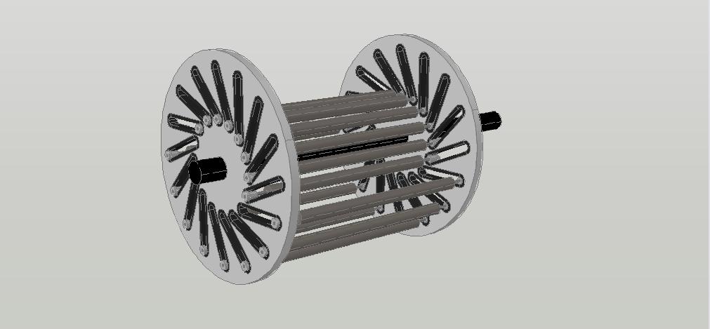
Fig. 4
At the beginning of the search for the possibilities of creating an environmentally friendly engine, it was considered the variant of rotor design corresponding to Fig. 4.
On this picture it can be seen the pair of identical disks which are rigidly mounted on the axis of rotation. Into each of the disks is embedded a large number of inclined paths that are uniformly distributed relative to the axis of rotation. In the space between the disks are placed movable loads of cylindrical form, at both ends of which there are wheels that ensure displacement of the loads along the inclined paths during rotation of the disks. The inclined paths enable formation of unequal-arm levers of rotation between the centers of masses of the loads relative to the axis of rotation of the disks. The displacement of the loads is produced as a result of the gravitational force exerted on their masses. For the optimum impact of gravitation the axis of rotation of the engine rotor must be located horizontally with respect to the surface of the Earth.
In order to determine the magnitude and the nature formation of the resulting rotational effort on the rotor shaft of the engine, that are provided by the force impact on the masses of movable loads only by gravitation field alone, it was made the calculation in a general form. At this, as initial data for the calculation, were adopted the following notations:
Fg — force of gravitational impact on the mass of any movable load;
Rmax and Rmin — the circumferences of the maximum and the minimum removal of the centers of masses of the loads relative to the axis of rotation of the engine rotor;
At the calculation the number of loads was taken equal to 16, and the ratio Rmax/Rmin was taken equal to 2.
The calculation, of course, showed with sufficient accuracy that the net torque, produced by all sixteen movable loads, is equal zero, that is this device, like any other similar to it, unable provide the prolonged rotation through use solely kinetic energy of the gravitational field. And this corresponds to the basic law of physics - to the law of conservation of energy, as well as to the property of the potential nature of the gravitational field which determines the equality of the work of any physical object to zero when it moves along a closed trajectory.
Rotation of the disks can begin and continue for a long time only under the influence of an external rotating force (external with respect to the impact of gravitation). After the cessation of the external influence the coupled disks can make a few turns, and, after that, the rotation ceases. The system inevitably comes to a state of stable equilibrium. Number of the possible positions at which the rotation of the disks may be finished is equal to the number of movable loads.
In result of the calculation are appeared in a general form (in accordance with the above notations of the initial data) the quantitative relationships between all the individual torques produced by each of the moving loads. It became clear, how the location of the center of mass of each individual load, during the process of rotor rotation, affects the magnitude and sign of the corresponding individual torque, incoming in overall sum of the net torque. At this was revealed the sector of rotation in which the impact of gravitation on the centers of masses of moving loads causes the greatest inhibitory affect, i.e. brings in the greatest negative contribution to the net torque.
Consider Figure 2, where this sector is designated by the symbols A8 – O – A11.
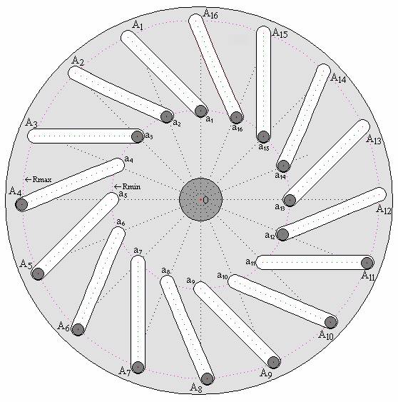
Here is depicted the cross section of the device, shown in Fig. 4, by a plane perpendicular to the axis of rotation and passing in the middle of the space between the coupled disks. The letter symbols (a1—a16 and A1— A16) denote the location of the centers of masses of the loads at their minimum and maximum removal (Rmin and Rmax) from the axis of rotation of the disk (from the point “O”). Rotating counter-clockwise is assumed as the positive direction of rotation.
During the movement of the loads in space of the sector A8 – O – A11, the moments of rotation created by their masses are negative in sign, and since the centers of their masses are moving here along the circumference of the maximum distance from the axis of rotation (Rmax) the magnitudes of these moments of rotation are maximum.
The results of the calculation made it possible to conclude that, if an external energy source counteracts the influence of gravitation on the masses of loads moving in this sector of rotation and, at this, the centers of their masses come near, as possible, to the axis of rotation of the rotor, the system will change its state. There will no longer be any states of stable equilibrium in such a system. The loads moving in the remaining sectors of rotation, whose centers of masses are connected by unequal-arm levers of rotation with the axis of the rotor, will provide the positive magnitude of the net torque on the motor shaft exceeding zero. The continual rotation of the disks will become possible. At this, the necessary condition for enabling prolonged rotation is that the magnitude of the net torque must overcome the total resistance to rotation produced by the payload on the motor shaft, friction, heating, and other factors that impede rotation.
On the basis of this conclusion, several engine variants were developed. The rotors of these engines were equipped with the movable loads outfitted with permanent magnets of annular or bar form. The stators of these engines, surrounding the outer surfaces of the movable loads, were also equipped with permanent magnets. At this, the geometric shapes of the stator magnets, and their location were chosen with taking into account the optimal interaction with the moving magnets of the rotor passing in front of them. In all versions of these engines the counteraction to the negative influence of gravitation on the masses of loads, during their moving in this sector of rotation, was realized by using the phenomenon of levitation of opposing magnets, that is the stationary magnets and the magnets moving above them interacted in the repulsion mode. Ascension (suspension) of the movable loads during their movement in this sector of rotation was accompanied with the approach of the centers of their masses to the axis of rotation of the rotor of the engine. Such interaction of the permanent magnets provided the creation of the initial rotating force on the rotor shaft of the motor due to the above reason. The interaction between stationary and moving magnets in the remaining rotation areas provided creation of the additional positive contribution to the net torque.
In the variants proposed on the early stages of designing the interaction of all the opposing magnets was repulsive. In the subsequent variants, it was found an opportunity to abandon from the use of the repulsion mode at interaction of opposing magnets in the most of other sectors of rotation, by replacing it with the mode of mutual attraction, except the sector, corresponding to the sector A8 – O – A11 (Fig. 2), in which was created the initial rotational force on the rotor shaft of the engine due to the use the phenomenon of levitation of magnets. The usage of the mode of mutual repulsion of magnets in this sector of rotation seemed inevitable, although even then it was clear that the efficiency of using permanent magnets in the repulsion mode was small, from point of view of force interaction, and included the danger of irreversible demagnetization of permanent magnets.
Ensuring the reliable absence of irreversible demagnetization was recommended not only through the use of magnetic materials with the highest coercive force, that is, the materials which are characterized by the highest ability to withstand the conditions causing demagnetization, as well as through the careful, relatively complex, experimental development. The need to implement these measures must inevitably lead to the significant rise in the cost of such engines and, consequently, must decrease in their competitiveness.
This drawback stimulated the searches of other environmentally friendly energy sources to provide the counteraction to gravitation in this sector of rotation of the engine rotor.
In Appendix 5 several options have been proposed for designing the rotors of hydraulic turbine engines. The design of the rotors of these engines, with the use of the identical coupled disks equipped by inclined paths for displacement of the movable loads (turbine blades) relative to the axis of rotation, basically resembles the devices explained with the help of Fig. 2.
The net torques on the shaft of such engines are formed not only by the sole force action on the rotor blades of the pressure of the falling water from above, that is typical for the conventional hydraulic turbine engines, but also by the direct impact of gravitation on the masses of the movable blades, the centers of masses of which are connected with the axis of rotation by the unequal-arm levers.
In these options of construction of rotors the counteraction to the negative influence of gravitation on the masses of loads, moving in the aforementioned sector of rotation, is realized by aid of the necessary redirection of the water falling from above. At this, the approaching of the centers of masses of the loads to the axis of rotation of the rotor, during their moving in this sector, is provided due to the appropriate placement of the stationary rigid body forming the paths, adequate for this purpose, for the moving along them of the additional wheels built-in the movable loads (turbine blades).
The question concerning the energy relationships that are arose during the intervention of a stationary rigid body to the process of motion of the rotor blades of the engines was not specifically considered in Appendix 5. However, it has served as an incentive for the subsequent thorough analysis of the nature and results of ensuring the counteraction to gravitation in this sector of rotation of the engine rotor, accompanied by the conversion of a part of the kinetic energy of the gravitational field (which without this intervention of the stationary rigid body would have to inhibit rotation) into the potential energy of elastic deformation of a stationary rigid body.
The Appendix 6 is devoted to setting out the explication of this question.
*
To facilitate the reading of this section of the site, at first is represented the description of the design variant of the rotor of the fuelless engine, the implementation of which is proposed on the basis of positive conclusions obtained as a result of the calculation of the net torque created on the shaft of a similar engine. As regard to the calculation technique, of the obtained calculation results and their explanations, proving the feasibility of such engines, it will be described afterwards.
*
* * *
Consider the Fig. 076.
The main difference between the design of this rotor and the device shown in Fig. 4 is that into the space of the aforementioned rotation sector is introduced the stationary rigid body, forming inclined paths for approaching of the movable loads with the axis of rotation of the rotor. The movable loads of this rotor are equipped with additional wheels for movement over the surfaces of the inclined paths of the stationary rigid body. At this, the number of the movable loads and corresponding number of the inclined paths, built into the disks, is assumed to be 10, rather than 16, and the ratio Rmax/Rmin is taken equal to 2.5, instead of 2, as it was earlier (These quantitative changes are not fundamental - they were adopted for convenience of calculation, which will be considered afterward.).
Structure of the movable load of cylindrical shape is explained with the help of Fig. 077.

The device of the stationary rigid body forming the inclined paths for moving the additional wheels of the movable loads is shown in Fig. 078.

The schematic representation of cross-section of the movable load in the space between the coupled disks, at its moving in the sector of rotation mentioned above, is explained with the aid of Fig. 079.
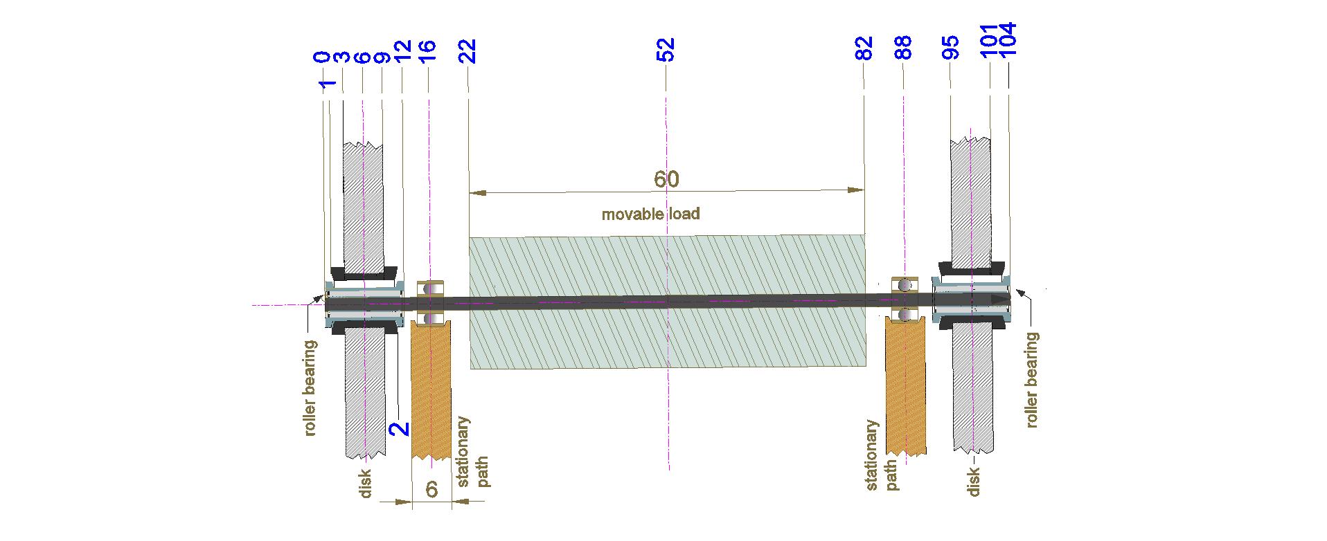
Here is shown the cross section of the rotor (depicted in Fig. 076) by the plane which, being parallel to the axis of rotation of the rotor, crosses the axis of one of the cylindrical loads at the moment of its movement along the inclined paths of the stationary rigid body. Relative distances between the elements of the structure are shown in conventional units, for example, - in centimetres.
*
* * *
Since in such devices the character of formation the net torque is repeated every time during the sequential rotation of the engine rotor by an angle equal to 360°/n, where n is number of inclined paths embedded in a disk, then in order to determine the magnitude and to understand the character of variations of the net torque during the whole process rotation, it is enough to investigate this question in the process of turning within only one such angle.
In our case, the number n was taken equal to 10, that is, the angle of rotation of the rotor of the engine, sufficient to obtain a complete picture of the nature of formation the resultant net torque, is 360°/10 = 36°. This angle was divided into 8 equal angular displacements (36°/8 = 4.5°). The state corresponding to Fig. 080 has been taken arbitrarily as the initial state for calculation of the net torque, and the calculation was fulfilled for this state at first. Then, the calculation was carried out 7 times after successive turn of the rotor (in the counterclockwise direction) by an angle of 4.5°. At this, of course, the stationary rigid body did not turn. Each time, the calculation was made, for comparison, at the presence and at the absence of the stationary solid body in the sector indicated above.
The data obtained as a result of the calculation are adduced below in Tables 1 to 8.
In Figure 080 is shown the initial state of the engine rotor, from which the calculation was started.
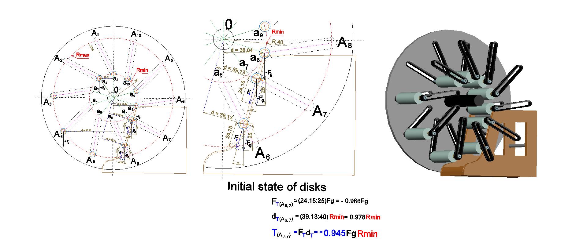
In Fig. 080, in its left part, the cross section of the rotor of the fuelless engine is shown, which was carried out similarly to the cross section shown in Fig. 2. Here, in addition to the notations for the locations of the centers of masses of the movable loads at their maximum and minimum distance (Rmax and Rmin) from the axis of rotation of the disks (from the point "O"), the outer contour of the stationary rigid body, placed in the above sector, is also shown. In this figure, one can see the location of the centers of masses of the movable loads, as well as the outer contours of two wheels of these loads (the wheels of larger diameter, serving for displacement along inclined paths embedded into the disks, and the wheels of smaller diameter intended for moving along the paths of the stationary rigid body). In the central part of Fig. 080 is shown the right lower sector of this cross section in an enlarged view (scale 1 : 1.8). In the right part of Fig. 080 is shown the three-dimensional image of the appearance of this rotor (together with the stationary rigid body) in the initial state for the calculation. At this, for clarity, the front disk of the rotor was removed, but the inclined paths of this disk were left at their places, and so you can see the movable loads with their wheels.
The torque formed by any individual load when moving in the right lower sector, where its center of gravity is forced to approach the axis of rotation of the rotor, is calculated by the formula:
Tn = FT×dn
The torque formed by any individual load when moving in the remaining sectors of rotation, i.e., in all sectors of rotation, where there is no the stationary rigid body, is calculated by the formula:
Tn = Fg×dn
Where:
Tn — individual torque (n — symbolic designation of the particular movable load);
Fg — the magnitude of the vector of gravitational action on the mass of any movable load;
FT — the magnitude of the component of the vector Fg determining the formation of the individual torque generated by the load during its moving along the paths of the stationary rigid body;
dn — the value of the lever arm of rotation, i.e., the magnitude of shortest distance between the direction of the vector (Fg, or FT) which forms the individual torque, and of the axis of engine rotation.
All magnitudes of the vectors and distances, shown in Fig. 080, are given in relative units, for example, - in centimeters. The calculation "in general form" is made so that these quantities are correlated with the values of Rmin and Rmax. Specific numerical values of these quantities are obtained by using the "AutoCAD" program tools, in accordance with the selected image scale. The ratio Rmax/Rmin in this calculation was accepted to be equal 2.5, in contrast to the calculation corresponding to Fig. 2, set forth in section Appendix 1 – Calculation in general form of net torque of the device analogous to "Indian wheel", where such ratio was assumed to be equal 2.
* * *
| Table 1, Fig. 080 Disks are in the initial state for calculations - there is no turn of the disks. |
|||
|---|---|---|---|
| In the space between the coupled disks there is no the stationary rigid body. |
In the sector A6 – O – A8 there is the stationary rigid body, which forms the guiding paths, the angle of inclination of which, relative to the vertical, is -15°. |
||
| Load | Individual torque Ti = Fg×di |
Load | Individual torque Ti = Fg×di, or Ti = FT×di |
| a1 | 0 | a1 | 0 |
| a2 | +Fg×di = +Fg(23.51:40)Rmin = +0.588FgRmin | a2 | +Fg×di = +Fg(23.51:40)Rmin = +0.588FgRmin |
| A3 | +Fg×di = +Fg(99.97:40)Rmin = +2.499FgRmin | A3 | +Fg×di = +Fg(99.97:40)Rmin = +2.499FgRmin |
| A4 | +Fg×di = +Fg(82.38:40)Rmin = +2.060FgRmin | A4 | +Fg×di = +Fg(82.38:40)Rmin = +2.060FgRmin |
| A5 | +Fg×di = +Fg(33.32:40)Rmin = +0.833FgRmin | A5 | +Fg×di = +Fg(33.32:40)Rmin = +0.833FgRmin |
| A6 | −Fg×di = −Fg(28.46:40)Rmin = −0.712FgRmin | A6 | −FT×di = −(24.15:25)Fg(39.13:40)Rmin = −0.945FgRmin |
| A7 | −Fg×di = −Fg(79.37:40)Rmin = −1.984FgRmin | A7 | −FT×di = −(24.15:25)Fg(39.13:40)Rmin = −0.945FgRmin |
| a8 | −Fg×di = −Fg(38.04:40)Rmin = −0.951FgRmin | a8 | −Fg×di = −Fg(38.04:40)Rmin = −0.951FgRmin |
| a9 | −Fg×di = −Fg(38.04:40)Rmin = −0.951FgRmin | a9 | −Fg×di = −Fg(38.04:40)Rmin = −0.951FgRmin |
| a10 | −Fg×di = −Fg(23.51:40)Rmin = −0.588FgRmin | a10 | −Fg×di = −Fg(23.51:40)Rmin = −0.588FgRmin |
| The net torque T = ∑ Ti = (+5.980 − 5.186)FgRmin = +0.794FgRmin |
The net torque T = ∑ Ti = (+5.980 − 4.380)FgRmin = +1.600FgRmin |
||
| Table 2, Fig. 081 The disks are turned at the angle 1/8×36° = 4.5°. |
|||
|---|---|---|---|
| In the space between the coupled disks there is no the stationary rigid body. |
In the sector A6 – O – A8 there is the stationary rigid body, which forms the guiding paths, the angle of inclination of which, relative to the vertical, is -15°. |
||
| Load | Individual torque Ti = Fg×di |
Load | Individual torque Ti = Fg×di, or Ti = FT×di |
| a1 | +Fg×di = +Fg(03.14:40)Rmin = +0.079FgRmin | a1 | +Fg×di = +Fg(03.14:40)Rmin = +0.079FgRmin |
| a2 | +Fg×di = +Fg(25.98:40)Rmin = +0.650FgRmin | a2 | +Fg×di = +Fg(25.98:40)Rmin = +0.650FgRmin |
| A3 | +Fg×di = +Fg(99.86:40)Rmin = +2.497FgRmin | A3 | +Fg×di = +Fg(99.86:40)Rmin = +2.497FgRmin |
| A4 | +Fg×di = +Fg(77.67:40)Rmin = +1.942FgRmin | A4 | +Fg×di = +Fg(77.67:40)Rmin = +1.942FgRmin |
| A5 | +Fg×di = +Fg(25.82:40)Rmin = +0.646FgRmin | A5 | +Fg×di = +Fg(25.82:40)Rmin = +0.646FgRmin |
| A6 | −Fg×di = −Fg(35.90:40)Rmin = −0.898FgRmin | A6 | −FT×di = −(24.15:25)Fg(39.13:40)Rmin = −0.945FgRmin |
| A7 | −Fg×di = −Fg(83.90:40)Rmin = −2.098FgRmin | A7 | −FT×di = −(24.15:25)Fg(39.13:40)Rmin = −0.945FgRmin |
| a8 | −Fg×di = −Fg(38.89:40)Rmin = −0.972FgRmin | a8 | −Fg×di = −Fg(38.89:40)Rmin = −0.972FgRmin |
| a9 | −Fg×di = −Fg(36.96:40)Rmin = −0.924FgRmin | a9 | −Fg×di = −Fg(36.96:40)Rmin = −0.924FgRmin |
| a10 | −Fg×di = −Fg(20.90:40)Rmin = −0.523FgRmin | a10 | −Fg×di = −Fg(20.90:40)Rmin = −0.523FgRmin |
| The net torque T = ∑ Ti = (+5.814 − 5.415)FgRmin = +0.399FgRmin |
The net torque T = ∑ Ti = (+5.814 − 4.309)FgRmin = +1.505FgRmin |
||
| Table 3, Fig. 082 The disks are turned at the angle 2/8×36° = 9°. |
|||
|---|---|---|---|
| In the space between the coupled disks there is no the stationary rigid body. |
In the sector A6 – O – A8 there is the stationary rigid body, which forms the guiding paths, the angle of inclination of which, relative to the vertical, is -15°. |
||
| Load | Individual torque Ti = Fg×di |
Load | Individual torque Ti = Fg×di, or Ti = FT×di |
| a1 | +Fg×di = +Fg(06.26:40)Rmin = +0.157FgRmin | a1 | +Fg×di = +Fg(06.26:40)Rmin = +0.157FgRmin |
| a2 | +Fg×di = +Fg(28.28:40)Rmin = +0.707FgRmin | a2 | +Fg×di = +Fg(28.88:40)Rmin = +0.707FgRmin |
| A3 | +Fg×di = +Fg(99.14:40)Rmin = +2.479FgRmin | A3 | +Fg×di = +Fg(99.14:40)Rmin = +2.479FgRmin |
| A4 | +Fg×di = +Fg(72.49:40)Rmin = +1.812FgRmin | A4 | +Fg×di = +Fg(72.49:40)Rmin = +1.812FgRmin |
| A5 | +Fg×di = +Fg(18.16:40)Rmin = +0.454FgRmin | A5 | +Fg×di = +Fg(18.16:40)Rmin = +0.454FgRmin |
| A6 | −Fg×di = −Fg(43.11:40)Rmin = −1.078FgRmin | A6 | −FT×di = −(24.15:25)Fg(39.13:40)Rmin = −0.945FgRmin |
| A7 | −Fg×di = −Fg(87.91:40)Rmin = −2.198FgRmin | A7 | −FT×di = −(24.15:25)Fg(39.13:40)Rmin = −0.945FgRmin |
| a8 | −Fg×di = −Fg(39.51:40)Rmin = −0.988FgRmin | a8 | −Fg×di = −Fg(39.51:40)Rmin = −0.988FgRmin |
| a9 | −Fg×di = −Fg(35.64:40)Rmin = −0.891FgRmin | a9 | −Fg×di = −Fg(35.64:40)Rmin = −0.891FgRmin |
| a10 | −Fg×di = −Fg(18.16:40)Rmin = −0.454FgRmin | a10 | −Fg×di = −Fg(18.16:40)Rmin = −0.454FgRmin |
| The net torque T = ∑ Ti = (+5.609 − 5.609)FgRmin = +0.000FgRmin |
The net torque T = ∑ Ti = (+5.609 − 4.223)FgRmin = +1.386FgRmin |
||
The note to the results of the calculations set out in Table 3:
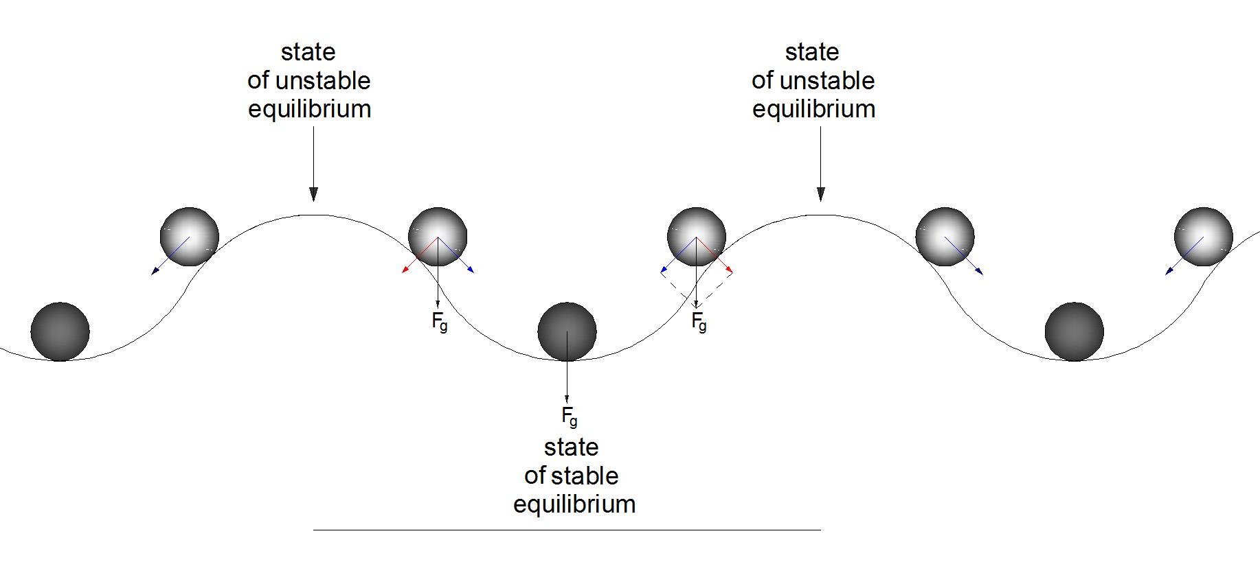
From the calculation results, given in the Table 3, it can be concluded that, if there is no the stationary rigid body in the space between the coupled disks, then, at the turn of the disks (in the counterclockwise direction) on the angle of 2/8×36° = 9°, relative to the “initial” state, in the such system is realized the state of stable equilibrium.
The possibility of short-term rotation of a device of similar design under the action only of gravitation can be compared with the possibility of moving a metal ball over the undulating surface, shown in Fig. 088, under the action only of gravity. Here are also alternated the states of stable and unstable equilibrium. The long-term movement of a ball along a similar surface can be ensured only due to the appropriate force action of another source of energy, other than gravitational one. After the cessation of the force action of the external energy source, a short-term inertial movement is possible, and then, starting from an arbitrary point on the surface, the movement can be continued under the action of gravity alone until to the inevitable stopping in the point where the state of stable equilibrium must be realized.
| Table 4, Fig. 083 The disks are turned at the angle 3/8×36° = 13.5°. |
|||
|---|---|---|---|
| In the space between the coupled disks there is no the stationary rigid body. |
In the sector A6 – O – A8 there is the stationary rigid body, which forms the guiding paths, the angle of inclination of which, relative to the vertical, is -15°. |
||
| Load | Individual torque Ti = Fg×di |
Load | Individual torque Ti = Fg×di, or Ti = FT×di |
| a1 | +Fg×di = +Fg(09.34:40)Rmin = +0.234FgRmin | a1 | +Fg×di = +Fg(09.34:40)Rmin = +0.234FgRmin |
| a2 | +Fg×di = +Fg(30.42:40)Rmin = +0.761FgRmin | a2 | +Fg×di = +Fg(30.42:40)Rmin = +0.761FgRmin |
| A3 | +Fg×di = +Fg(97.80:40)Rmin = +2.445FgRmin | A3 | +Fg×di = +Fg(97.80:40)Rmin = +2.445FgRmin |
| A4 | +Fg×di = +Fg(66.86:40)Rmin = +1.672FgRmin | A4 | +Fg×di = +Fg(66.86:40)Rmin = +1.672FgRmin |
| A5 | +Fg×di = +Fg(10.39:40)Rmin = +0.260FgRmin | A5 | +Fg×di = +Fg(10.39:40)Rmin = +0.260FgRmin |
| A6 | −Fg×di = −Fg(50.06:40)Rmin = −1.252FgRmin | A6 | −FT×di = −(24.15:25)Fg(39.13:40)Rmin = −0.945FgRmin |
| A7 | −Fg×di = −Fg(91.38:40)Rmin = −2.285FgRmin | A7 | −FT×di = −(24.15:25)Fg(39.13:40)Rmin = −0.945FgRmin |
| a8 | −Fg×di = −Fg(39.88:40)Rmin = −0.997FgRmin | a8 | −Fg×di = −Fg(39.88:40)Rmin = −0.997FgRmin |
| a9 | −Fg×di = −Fg(34.11:40)Rmin = −0.853FgRmin | a9 | −Fg×di = −Fg(34.11:40)Rmin = −0.853FgRmin |
| a10 | −Fg×di = −Fg(15.31:40)Rmin = −0.383FgRmin | a10 | −Fg×di = −Fg(15.31:40)Rmin = −0.383FgRmin |
| The net torque T = ∑ Ti = (+5.372 − 5.770)FgRmin = −0.398FgRmin |
The net torque T = ∑ Ti = (+5.372 − 4.123)FgRmin = +1.249FgRmin |
||
| Table 5, Fig. 084 The disks are turned at the angle 4/8×36° = 18°. |
|||
|---|---|---|---|
| In the space between the coupled disks there is no the stationary rigid body. |
In the sector A6 – O – A8 there is the stationary rigid body, which forms the guiding paths, the angle of inclination of which, relative to the vertical, is -15°. |
||
| Load | Individual torque Ti = Fg×di |
Load | Individual torque Ti = Fg×di, or Ti = FT×di |
| a1 | +Fg×di = +Fg(12.36:40)Rmin = +0.309FgRmin | a1 | +Fg×di = +Fg(12.36:40)Rmin = +0.309FgRmin |
| a2 | +Fg×di = +Fg(32.36:40)Rmin = +0.809FgRmin | a2 | +Fg×di = +Fg(32.36:40)Rmin = +0.809FgRmin |
| A3 | +Fg×di = +Fg(95.86:40)Rmin = +2.397FgRmin | A3 | +Fg×di = +Fg(95.86:40)Rmin = +2.397FgRmin |
| A4 | +Fg×di = +Fg(60.82:40)Rmin = +1.521FgRmin | A4 | +Fg×di = +Fg(60.82:40)Rmin = +1.521FgRmin |
| A5 | +Fg×di = +Fg(02.55:40)Rmin = +0.064FgRmin | A5 | +Fg×di = +Fg(02.55:40)Rmin = +0.064FgRmin |
| A6 | −Fg×di = −Fg(56.69:40)Rmin = −1.417FgRmin | A6 | −FT×di = −(24.15:25)Fg(39.13:40)Rmin = −0.945FgRmin |
| A7 | −Fg×di = −Fg(94.29:40)Rmin = −2.357FgRmin | A7 | −FT×di = −(24.15:25)Fg(39.13:40)Rmin = −0.945FgRmin |
| a8 | −Fg×di = −Fg(40.00:40)Rmin = −1.000FgRmin | a8 | −Fg×di = −Fg(40.00:40)Rmin = −1.000FgRmin |
| a9 | −Fg×di = −Fg(32.36:40)Rmin = −0.809FgRmin | a9 | −Fg×di = −Fg(32.36:40)Rmin = −0.809FgRmin |
| a10 | −Fg×di = −Fg(12.36:40)Rmin = −0.309FgRmin | a10 | −Fg×di = −Fg(12.36:40)Rmin = −0.309FgRmin |
| The net torque T = ∑ Ti = (+5.100 − 5.892)FgRmin = −0.792FgRmin |
The net torque T = ∑ Ti = (+5.100 − 4.008)FgRmin = +1.092FgRmin |
||
| Table 6, Fig. 085 The disks are turned at the angle 5/8×36° = 22.5°. |
|||
|---|---|---|---|
| In the space between the coupled disks there is no the stationary rigid body. |
In the sector A6 – O – A8 there is the stationary rigid body, which forms the guiding paths, the angle of inclination of which, relative to the vertical, is -15°. |
||
| Load | Individual torque Ti = Fg×di |
Load | Individual torque Ti = Fg×di, or Ti = FT×di |
| a1 | +Fg×di = +Fg(15.31:40)Rmin = +0.383FgRmin | a1 | +Fg×di = +Fg(15.31:40)Rmin = +0.383FgRmin |
| a2 | +Fg×di = +Fg(34.11:40)Rmin = +0.853FgRmin | a2 | +Fg×di = +Fg(34.11:40)Rmin = +0.853FgRmin |
| A3 | +Fg×di = +Fg(93.33:40)Rmin = +2.333FgRmin | A3 | +Fg×di = +Fg(93.33:40)Rmin = +2.333FgRmin |
| A4 | +Fg×di = +Fg(54.39:40)Rmin = +1.360FgRmin | A4 | +Fg×di = +Fg(54.39:40)Rmin = +1.360FgRmin |
| A5 | +Fg×di = −Fg(05.30:40)Rmin = −0.133FgRmin | A5 | −FT×di = −(10.31:25)Fg(92.44:40)Rmin = −0.953FgRmin |
| A6 | −Fg×di = −Fg(62.98:40)Rmin = −1.575FgRmin | A6 | −FT×di = −(24.15:25)Fg(39.13:40)Rmin = −0.945FgRmin |
| A7 | −Fg×di = −Fg(96.61:40)Rmin = −2.415FgRmin | A7 | −FT×di = −(24.15:25)Fg(39.13:40)Rmin = −0.945FgRmin |
| a8 | −Fg×di = −Fg(39.88:40)Rmin = −0.997FgRmin | a8 | −Fg×di = −Fg(39.88:40)Rmin = −0.997FgRmin |
| a9 | −Fg×di = −Fg(30.42:40)Rmin = −0.761FgRmin | a9 | −Fg×di = −Fg(30.42:40)Rmin = −0.761FgRmin |
| a10 | −Fg×di = −Fg(09.34:40)Rmin = −0.234FgRmin | a10 | −Fg×di = −Fg(09.34:40)Rmin = −0.234FgRmin |
| The net torque T = ∑ Ti = (+4.929 − 6.115)FgRmin = −1.186FgRmin |
The net torque T = ∑ Ti = (+4.929 − 4.835)FgRmin = +0.094FgRmin |
||
| Table 7, Fig. 086 The disks are turned at the angle 6/8×36° = 27°. |
|||
|---|---|---|---|
| In the space between the coupled disks there is no the stationary rigid body. |
In the sector A6 – O – A8 there is the stationary rigid body, which forms the guiding paths, the angle of inclination of which, relative to the vertical, is -15°. |
||
| Load | Individual torque Ti = Fg×di |
Load | Individual torque Ti = Fg×di, or Ti = FT×di |
| a1 | +Fg×di = +Fg(18.16:40)Rmin = +0.454FgRmin | a1 | +Fg×di = +Fg(18.16:40)Rmin = +0.454FgRmin |
| a2 | +Fg×di = +Fg(??.??:40)Rmin = +?.???FgRmin | a2 | +Fg×di = +Fg(66.99:40)Rmin = +1.675FgRmin |
| A3 | +Fg×di = +Fg(90.23:40)Rmin = +2.256FgRmin | A3 | +Fg×di = +Fg(90.23:40)Rmin = +2.256FgRmin |
| A4 | +Fg×di = +Fg(47.66:40)Rmin = +1.192FgRmin | A4 | +Fg×di = +Fg(47.66:40)Rmin = +1.192FgRmin |
| A5 | +Fg×di = −Fg(13.12:40)Rmin = −0.328FgRmin | A5 | −FT×di = −(17.22:25)Fg(76.78:40)Rmin = −1.323FgRmin |
| A6 | −Fg×di = −Fg(68.88:40)Rmin = −1.722FgRmin | A6 | −FT×di = −(24.15:25)Fg(39.13:40)Rmin = −0.945FgRmin |
| A7 | −Fg×di = −Fg(98.34:40)Rmin = −2.459FgRmin | A7 | −Fg×di = −Fg(35.64:40)Rmin = −0.891FgRmin |
| a8 | −Fg×di = −Fg(39.51:40)Rmin = −0.988FgRmin | a8 | −Fg×di = −Fg(39.51:40)Rmin = −0.988FgRmin |
| a9 | −Fg×di = −Fg(28.28:40)Rmin = −0.707FgRmin | a9 | −Fg×di = −Fg(28.28:40)Rmin = −0.707FgRmin |
| a10 | −Fg×di = −Fg(06.26:40)Rmin = −0.157FgRmin | a10 | −Fg×di = −Fg(06.26:40)Rmin = −0.157FgRmin |
| The net torque T = ∑ Ti = (+?.??? − 6.361)FgRmin = ??.???FgRmin |
The net torque T = ∑ Ti = (+5.577 − 5.011)FgRmin = +0.566FgRmin |
||
The note to the results of the calculations set out in Table 7:
At examining the Fig. 086, it can be seen that in the state corresponding to the turn of the disks relative to the initial state by the angle of 6/8×36° = 27° the dashed line of crimson color connecting the points a2 and A2 is positioned horizontally. This testifies about the horizontal position of the axes of the corresponding inclined paths embedded into the coupled disks. At the absence of the stationary rigid body in the above space between the coupled disks this state is unstable. If by using an external force such a device is turned so that the line a2 ... A2 is located horizontally, and after that the further impact of this force is finished, then the unstable of this state must manifest itself. Therefore, in this case, at the absence of a stationary rigid body in the system, the location of the center of mass of the load on the axis a2 ... A2 cannot be determined, i.e., it is impossible accurately determine the length of the corresponding lever arm of rotation, and, therefore, it is not possible to calculate the individual torque.
However, at the presence of the stationary rigid body, as it follows from the entire calculation, the ceaseless rotational force is created. The net torque ensures the prolonged rotation. At this, the centers of masses of the movable loads can be characterized by a certain angular velocity and rotational inertia. The numerical values of these characteristics of movement of the loads cannot be determined without knowing a particular device of a real engine. It can be made only some assumptions.
Let us consider the Fig. 089, illustrating the state of rotation at which the line a2 ... A2 has approached, but has not yet reached the horizontal position.
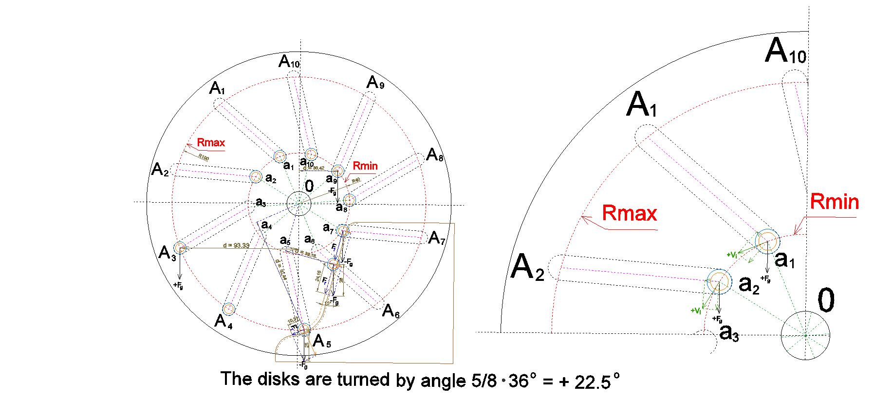
In the right-hand part of this figure is shown in enlarged view the cross section of the sector A10 – O – A2 of the engine rotor, at the moment when the disks are rotated by an angle of 5/8×36° = 22.5° relative to the state accepted for calculations as the “initial”. At this is assumed that rotation with a certain angular velocity does indeed occur. As a result of the continuous rotation of the disks, the centers of masses of the moving loads are subjected to action of the tangential velocity vectors shown in the figure with the arrows of green color, labeled +Vi. In spite of the fact that the actual magnitude of the angular velocity, at such a calculation “in general form” is unknown, it can be safely assumed that the trajectory of the displacement of the centers of masses of the loads in the course of their movement in this sector of rotation of the rotor disks will differ from the path along the circumference of Rmin. As a result of the influence of the components of the tangential velocity vectors +Vi directed along the axes of inclined paths embedded in the disks, the centers of masses of the loads moving in this sector will be shifting towards the circumference Rmax. Due to this displacement, the arms of the rotation levers will be getting lengthened and, accordingly, the individual moments of rotation of the loads moving here will be getting increased. The process of gradual shifting of the centers of masses of the loads towards the circumference of Rmax will begin immediately after entering into the sector A10 – O – A2 and will increase as the line a2 ... A2 approaches to the horizontal state. All this allows us to presume that at the turn of the disks relative to the initial state by an angle of 5/8×36° = 22.5°, that is, when the axes of the inclined paths built into the disks (denoted on the Fig. 086 by the dashed line connecting the points a2 and A2) will be located horizontally, the center of mass of the load moving along this paths will be near the middle of the distance between Rmin and Rmax. Therefore, in Table 7, at calculating the individual torque of the load a2, moving under the conditions of the presence of the stationary rigid body, the length of the arm of the rotation lever d was assumed equal to the number 66.99 rather than 35.64, as it could be for the load a2 in the case of absence of the stationary rigid body.
| Table 8, Fig. 087 The disks are turned at the angle 7/8×36° = 31.5°. |
|||
|---|---|---|---|
| In the space between the coupled disks there is no the stationary rigid body. |
In the sector A6 – O – A8 there is the stationary rigid body, which forms the guiding paths, the angle of inclination of which, relative to the vertical, is -15°. |
||
| Load | Individual torque Ti = Fg×di |
Load | Individual torque Ti = Fg×di, or Ti = FT×di |
| a1 | +Fg×di = +Fg(20.90:40)Rmin = +0.523FgRmin | a1 | +Fg×di = +Fg(20.90:40)Rmin = +0.523FgRmin |
| A2 | +Fg×di = +Fg(99.46:40)Rmin = +2.487FgRmin | A2 | +Fg×di = +Fg(99.46:40)Rmin = +2.487FgRmin |
| A3 | +Fg×di = +Fg(86.57:40)Rmin = +2.164FgRmin | A3 | +Fg×di = +Fg(86.57:40)Rmin = +2.164FgRmin |
| A4 | +Fg×di = +Fg(40.61:40)Rmin = +1.015FgRmin | A4 | +Fg×di = +Fg(40.61:40)Rmin = +1.015FgRmin |
| A5 | +Fg×di = −Fg(20.85:40)Rmin = −0.521FgRmin | A5 | −FT×di = −(22.79:25)Fg(51.75:40)Rmin = −1.180FgRmin |
| A6 | −Fg×di = −Fg(74.36:40)Rmin = −1.859FgRmin | A6 | −FT×di = −(24.15:25)Fg(39.13:40)Rmin = −0.945FgRmin |
| a7 | −Fg×di = −Fg(36.96:40)Rmin = −0.924FgRmin | a7 | −Fg×di = −Fg(36.96:40)Rmin = −0.924FgRmin |
| a8 | −Fg×di = −Fg(38.89:40)Rmin = −0.972FgRmin | a8 | −Fg×di = −Fg(38.89:40)Rmin = −0.972FgRmin |
| a9 | −Fg×di = −Fg(25.98:40)Rmin = −0.650FgRmin | a9 | −Fg×di = −Fg(25.98:40)Rmin = −0.650FgRmin |
| a10 | −Fg×di = −Fg(03.50:40)Rmin = −0.088FgRmin | a10 | −Fg×di = −Fg(03.50:40)Rmin = −0.088FgRmin |
| The net torque T = ∑ Ti = (+6.189 − 5.014)FgRmin = +1.175FgRmin |
The net torque T = ∑ Ti = (+6.189 − 4.759)FgRmin = +1.430FgRmin |
||
| Table 9 (Summary table of calculation results.) |
||||
|---|---|---|---|---|
| № Table |
№ Figure |
The turn angle of the disks |
In the space between the coupled disks there is no the stationary rigid body. ..................... The resultant net torque T = ∑ Ti = |
In the sector A6 – O – A8, there is the stationary rigid body. ..................... The resultant net torque T = ∑ Ti = |
| 1 | Fig. 080 | The initial state (There is no turn of the disks.) |
+0.794FgRmin | +1.600FgRmin |
| 2 | Fig. 081 | 1/8×36° = 4.5° | +0.399FgRmin | +1.505FgRmin |
| 3 | Fig. 082 | 2/8×36° = 9° | +0.000FgRmin State of stable equilibrium |
+1.386FgRmin |
| 4 | Fig. 083 | 3/8×36° = 13.5° | −0.398FgRmin | +1.249FgRmin |
| 5 | Fig. 084 | 4/8×36° = 18° | −0.792FgRmin | +1.092FgRmin |
| 6 | Fig. 085 | 5/8×36° = 22.5° | −1.186FgRmin | +0.094FgRmin |
| 7 | Fig. 086 | 6/8×36° = 27° | ??.???FgRmin State of unstable equilibrium |
+0.566FgRmin |
| 8 | Fig. 087 | 7/8×36° = 31.5° | +1.175FgRmin | +1.430FgRmin |
| The average value of the resulting net torque of the engine rotor, which contains in the sector A6 – O – A8 the stationary rigid body which forms the guiding paths, the angle of inclination of which relative to the vertical is equal to -15°, is: TAVG = (∑ T ) : 8 = +1.115FgRmin. |
||||
* * *
In Fig. 090 the results of calculations are shown in graphical form.
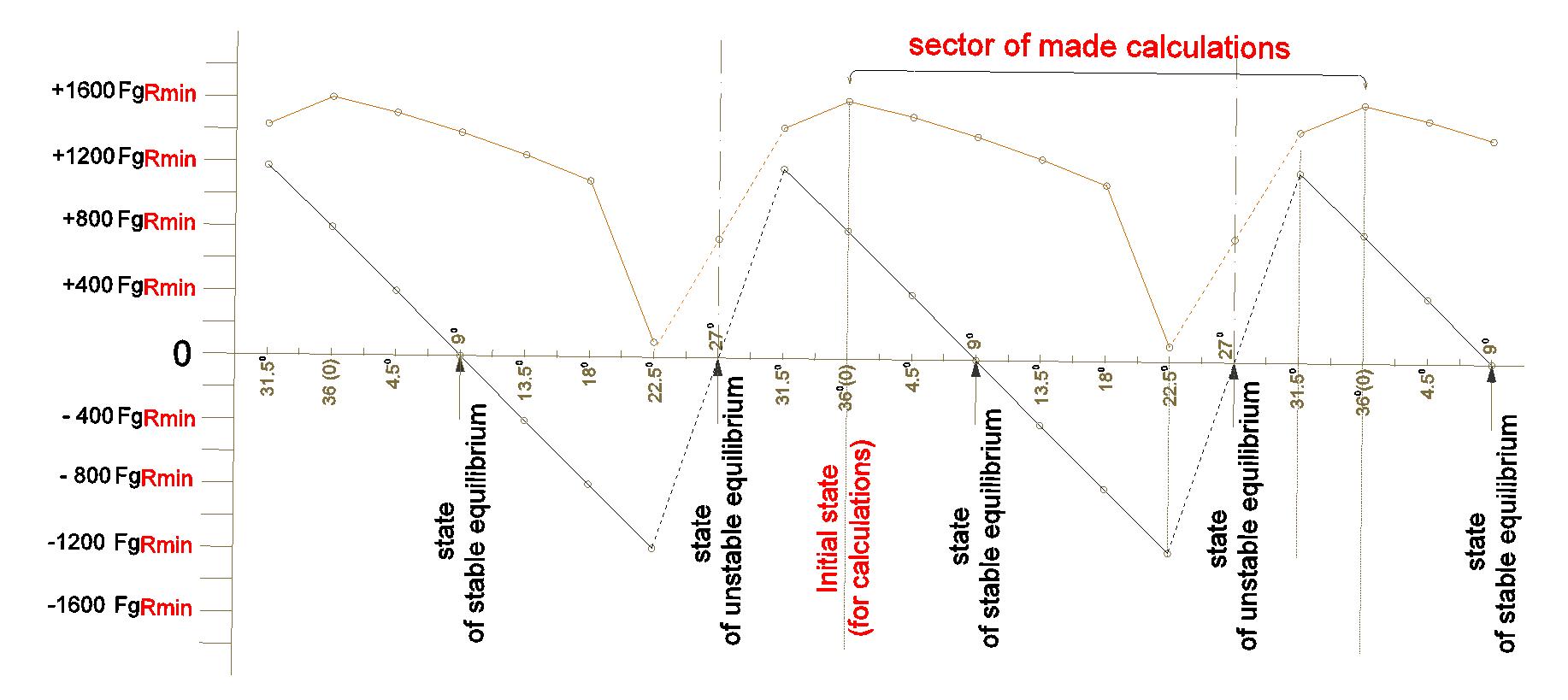
On the horizontal axis of the graph are marked and labeled the values of the turn angles of the disks relative to the state taken as the “initial” for the calculation. The distances plotted on the vertical allow estimate the values and directions of the resultant net torques arising in the positions corresponding to the turn angles of the disks. The counter-clockwise rotation of the engine rotor is accepted as the positive direction of rotation. That is indicated by the signs “+”. The values of the rotational impacts (of the resultant net torques) are indicated in general view - with the aid of literal symbols accompanied by the numerical values, adduced in relative units. If necessary use the calculation results to evaluate the corresponding parameters of a real engine of similar construction, the symbols Fg and Rmin should be substituted with their specific numerical values. In addition to the sector of rotation for which the calculations were performed, on the graph are also partly shown the adjacent areas of rotation in which the pattern of formation of the resulting net torque is repeated.
The graph allows us to compare the character of the changes in the values of the resultant net torques during the rotation of the engine rotor at the absence and at the presence into the specific space between the coupled disks of the stationary rigid body which forms the guiding paths for the additional wheels of the movable loads.
The broken curve, shown on the graph by the inclined rectilinear segments of black color, characterizes the change in the magnitude of the resultant net torque on the rotor shaft of the engine, depending on the angle of turn of the disks during the rotation process at the absence of the stationary rigid body. The states at which the disks are turned by an angle equal to 9° relative to the “initial state” are the states of stable equilibrium. If the rotation of the disks arises as a result of a force action originating from some other source of energy, differing from the gravitational source, then, after the cessation of this action, the rotation must be inevitably ceased in one of these states of stable equilibrium. In this case, the termination of rotation occurs as a result of the force action of gravitation, which remains the only source of energy that affects the rotation of the engine rotor. The states at which the disks are turned by an angle equal to 27° relative to the “initial state” are the states of unstable equilibrium.
The curve shown in the graph by the inclined rectilinear segments of brown color characterizes the change in the magnitude of the resultant net torque on the rotor shaft of the engine, depending on the angle of turn of the disks during the rotation process at the presence of the stationary rigid body. The nature of this curve and its location only in the upper (positive) side of the graph testify that, at the abovementioned arrangement of a stationary rigid body, the rotating force is provided for any value of the angle of rotation of the disks. In this case, the intervention of the stationary rigid body in the process of formation the trajectory of the motion of the centers of masses of the movable loads leads to the exclusion of the states of stable and unstable equilibrium. And although the boundary line of the resulting net torques, shown in the graph, is uneven, it covers the significant area of positive values, indicating the possibility of ensuring the continual rotation of the engine rotor, initiated by the action of gravitation alone.
* * *
The calculation of the values of the resulting net torques, arising on the rotor shaft of the engine at the absence of the stationary rigid body in the space between the rotor disks (the calculation performed here only for comparison with the corresponding date at the presence of the stationary rigid body), confirmed the calculation conclusions made at the initial stage designing of the gravity-magnetic engines, set forth in the Section 4 (Findings from the calculation) of this site.
The calculation showed, with sufficient accuracy, that when the gravitational field alone affects masses of moving loads, the resultant net torque created by all movable loads is zero. This is corresponded and explained by the law of conservation of energy. The behavior of this system is determined by the influence of the single energy source, in this sense it is an isolated one, that is, for such a system, the basic condition necessary for the applicability of the law of conservation of energy is met.
Rotation of the disks can be started and continued for a long time only under the influence of an external rotational force (external to gravitation). After cessation the external impact, the disks can make several revolutions, after which the rotation must be inevitably stopped due to influence of gravitation. In such case, the system comes to a state of stable equilibrium. The number of the possible positions of disks stoppages, at which the state of stable equilibrium is realized, is equal to the number of the movable loads.
The possibility of short-term rotation of such rotor under the influence of gravitation alone, after the termination of the additional force action of the external energy source, can be compared with the possibility of the movement of a metal ball along the undulating surface, shown in Fig. 088 (See note to table 3).
As a result of fulfil the calculation, quantitative relationships between all the values of the individual torques created by each of the movable loads were obtained, depending on its location during the rotation of the disks. At this, was revealed the sector of rotation of the rotor, in which the impact of gravitation on the centers of masses of the moving loads exerts the greatest inhibitory action, i.e., contributes the greatest negative contribution into the resultant net torque. Understanding this factor makes it possible to determine the direction of input of the external force from another source of energy for the optimal counteraction to gravitation in this part of the space occupied by the motor rotor.
The existence of stable equilibrium states in which the rotation of such a rotor is inevitably ceased, by the force impact of gravitation that solely operates in such a system, can be also explained by another reason which also corresponds to the law of conservation of energy and is a consequence of it.
From the consideration of the above figures, which depict the cross section of the engine rotor, it follows, that at the moments of turning the disks by the angles at which stable states are arisen, the design of the engine rotor turns out to be symmetrical with respect to the plane that runs vertically along the axis of rotor rotation. At this, as a result of the impact of gravitation on the masses of the movable loads, the loads, located to the left from the vertical plane, make the positive contribution into the net torque of an engine rotor (that is, they create rotating force action to counterclockwise), but the loads located to the right from the vertical, make the negative contribution into the net torque (that brakes the rotation). The symmetry of such states is manifested in the equality of the summary positive and negative rotational impacts and, thereby, ensures the equality to the zero of the resulting net torque on the rotor shaft of the engine.
*
The reliable formation of the resultant net torque as a result of the described above intervention of the stationary rigid body into the trajectory of displacement of the movable loads of the rotor can be explained as follows.
When calculating the formation of the resultant net torque without the intervention of the stationary rigid body in the trajectory of the motion of the loads, it was assumed that only the impact of gravitation on the masses of moving loads participates in the process of creating the rotatory force on the rotor shaft of the engine. The influences which must inhibit rotation, such as friction, the payload on the engine shaft, and any other reasons of energy losses, were not taken into account. At such conditions, the examined physical system can be considered isolated, i.e., subjected to the law of conservation of energy. This explains the inevitability of cessation of rotation after the cessation of the rotatory impacts from other sources of energy.
The intervention of the elastic energy of the stationary rigid body into the process of the force action of the kinetic energy of gravitation on the masses of moving loads disrupts the isolation of the system, and, consequently, removes the restriction associated with the law of conservation of energy.
The stationary rigid body changes the trajectory of the movement of the loads so, that the part of the kinetic energy of the gravitational action on the masses of the moving loads, which would have to hamper the rotation in the counterclockwise direction (that is, to make the negative contribution into the net torque, ensuring its zeroing), does not participate in the force action on rotation of the coupled rotor disks, but is transformed into the potential energy of elasticity of the stationary rigid body. As a result of intervention of the stationary rigid body, the positive contribution of the individual rotatory forces produced by the masses of the moving loads into the total sum of the torques exceeds the negative contribution, braking rotation of the coupled rotor disks. Due to this, all of the states of stable and unstable equilibrium are eliminated, and the constant rotatory impact is created on the rotor shaft of the engine.
*
In Fig. 091 are shown, for comparison, two images of the cross sections of the right lower sector of the space between the coupled disks in the state of turn of the disks by angle 5/8×36° = 22.5° relative to the initial state. At this, the image placed on the left side of the figure pertains to the case at which there is no the stationary rigid body within the space between the coupled disks.

At absence of the stationary rigid body, the trajectory of displacement of the centers of masses of the loads moving in this sector passes along the circumference Rmax. In this case, the entire magnitude of the vector of gravitational action on the mass of any moving load (In Fig. 091 this magnitude is indicated by the symbol “-Fg”.), multiplied by the length of the lever arm of rotation, that is, by the value of the shortest distance from the direction of the action line of this vector to the axis of rotation of the engine rotor (In Fig. 091 this value is indicated by the symbol “d”.), represents the value of the individual torque generated by the specific load in the particular point of location of its center of mass. Impact of gravitation on the masses of the loads, during their movement in this sector, is such that it counteracts rotor rotation counter-clockwise. Therefore, before the symbol “Fg” in Fig. 091 is entered the sign “-”.
The cross-sectional image of this sector, shown on the right-hand side of Fig. 091, includes the stationary rigid body that forms the guiding paths for the additional wheels of the movable loads. Intervention of these paths changes the movement trajectory of the loads. The centers of masses of the movable loads, instead of moving along the circumference of the maximum distance from the axis of rotation of the rotor (Rmax), move, at first, along the small path section of curvilinear form (near the point A5), but after that - throughout the long section of rectilinear, inclined path that brings them closer to the axis of rotation of the rotor, until the point from which the motion continues along the circle of the minimum distance from the axis of rotation (Rmin). Further, the movement of the loads continues already without intervention of the paths of the stationary rigid body.
In Fig. 091 is shown that, as a result of such intervention of the stationary rigid body into the space between the coupled rotor disks, vector -Fg can be represented by two components: the component -FT, directed tangentially to the surface of the stationary rigid body, and the component directed perpendicularly towards it. The component -FT is shown in Fig. 091 in form of the arrow of blue color, and the second component is shown by the arrow of red color. As a result of the intervention of the stationary rigid body into the process of movement of the loads, the creation of the negative rotatory force in this rotation sector (which inhibits rotation) is implemented by means of not the whole magnitude of the vector -Fg, but by means of the smaller value – that is corresponding to its component -FT. The value corresponding to the second component of the vector -Fg, that is, the component which acts on the stationary rigid body is neutralized in accordance with the third law of classical mechanics[36]. At this, not all the kinetic energy of the gravitational impact on the masses of the moving loads is expended on the formation of the force that inhibits rotation, but only a part of it. The second part of it is transformed into the potential energy of elasticity of the stationary rigid body[37].
Comparison of the magnitude of vector -Fg and the distances of lever arms of rotation d, which characterize the movement of the loads in this sector of rotation at the absence of the stationary rigid body, with corresponding to them the magnitude of vector -FT and values of d, which are formed during of the movement these loads along the main (prolonged, rectilinear) section of the path, determined by the geometric shape and emplacement of the stationary rigid body, proves that intervention of the stationary rigid body results to significant reduction of the individual torques created by these loads and, consequently, to the corresponding decrease of the negative component in the total sum of the net torque created on the shaft of the engine rotor.
However, on the small curvilinear segment of the path (near the point A5 in Fig. 091), the lengths of distances “d” are much larger than the corresponding values which arise at absence of the stationary rigid bogy. And although on this segment of the path the value of the component -FT also decreases, and to a much greater extent than on the rectilinear part of the path, nevertheless this segment of the path somewhat reduces the positive effect of introducing the stationary rigid body. But without this small curvilinear segment of the path there would be a sharp collision of the surfaces of the wheels of the moving load with the surfaces of the rectilinear inclined paths at every moment of the meeting. This would lead to significant weakening of the rotational inertia and to decrease the angular speed of the circular motion. Therefore, the smooth transition from the trajectory of motion along the circumference Rmax to motion along the rectilinear inclined paths formed by the stationary rigid body is seemed necessary. At this, it is desirable that the length of the transitional segment of the path would be as small as possible. Apparently, the optimal value of this length should be determined experimentally, in the process of experimental testing.
*
Thus, due to aforesaid introduction of the stationary rigid body into the space between the coupled rotor disks, the magnitude of the negative component in the net torque generated on the rotor shaft of the engine is decreased, the states of stable and unstable equilibrium are excluded, and, ultimately, the prolonged rotation of the engine is ensured, so long as and as much as the resultant net torque exceeds the braking efforts that may be caused by payload on the motor shaft, by friction, and also by other possible sources, as well as it is natural for any engine.
* * *
In accordance with the calculation results set forth in Table 9, the average value of the net torque of the engine rotor, which contains in the sector A6 – O – A8 the stationary rigid body that forms the rectilinear guiding paths, the angles of inclination of which relative to the vertical -15°, is:
TAVG = +1.115FgRmin
This mathematical expression, presented in a general form, allows us to make a numerical estimate of the resultant rotational impact (the net torque) by substituting into it specific numerical values of the corresponding characteristics of the real device.
Vg = πRg2Lg = 3.14⋅0.52dm2⋅10.0dm = 7.9dm3
Fg = YgVg = 7kg/dm3⋅7.9dm3 = 55kg,
That is, with such initial data, the force of gravity of the load Fg ≈ 55kgf.
TAVG = +1.115FgRmin = +1.115⋅55kgf⋅0.2m ≈ 12kgf⋅m,
that corresponds to 118 newton-metre (N·m).
Vg = πRg2Lg = 3.14⋅1.02dm2⋅6.0dm = 19dm3
Fg = YgVg = 7kg/dm3⋅19dm3 = 133kg,
That is, with such initial data, the force of gravity of the load Fg ≈ 133kgf.
TAVG = +1.115FgRmin = +1.115⋅133kgf⋅0.4m ≈ 59kgf⋅m,
that corresponds to 578 newton-metre (N·m).
*
As it can be seen from the above examples, the magnitude of the resultant net torque, as compared to the overall dimensions of the device, is relatively small. And although the design of the proposed device theoretically allows increase in its overall dimensions, including increase of the masses of movable loads, and, thereby, increase of the resultant net torque on the rotor shaft of the engine, at the real designing, this possibility will be limited by the requirement of ensuring the durability of the entire structure. However, such a method of productive use of the kinetic energy of gravitational action includes the real possibility of further increasing the resultant torque due to joint use gravitational energy with other renewable energy source. For example, it is possible additional use interaction energy of the permanent magnets of the rotor and the stator in the mutual attraction mode, or additional use the kinetic energy of the falling water.
*
* * *
Thus, here is shown one of the possibilities for creating a fuelless engine (gravity engine), the operation of which is provided by the force action of the kinetic energy of the gravitational field with involvement the energy of elastic deformation of a stationary rigid body.
The second, useful, consequence of the results of this designing of the rotor of the fuelless engine is in that the found possibility of weakening the negative effect of gravitation (hindering the rotation) allows us to abandon from use, for these purposes, of permanent magnets in the mode of mutual repulsion, that is, to abandon from use of the levitation of permanent magnets, that has been seemed inevitable in the early stages of designing of rotors for gravitational-magnetic engines. At this, the combination of the above method of using the stationary rigid body, during movement of the loads in the right lower sector of rotation of the rotor, with using of permanent magnets in the remaining rotation sectors, at their force interaction in the mode of mutual attraction, can significantly increase the resultant net torque on the shaft of engine rotor. The opportunity to do without the use of permanent magnets in the mode of mutual repulsion will simplify the experimental development, and, in general, can significantly reduce the cost of the development and manufacture of gravitational-magnetic engines. The use of the stationary rigid body, with taking into account the above recommendations regarding the formation of paths for additional wheels of mobile loads, can also increase the efficiency of using the kinetic energy of gravitation in the designs of the hydraulic motor rotors proposed in the section 20 of this site.
This Chapter was added on 12 June, 2017